
1. 事前準備
ARCore 平台可讓您在行動裝置上建構擴增實境 (AR) 應用程式。ARCore 透過不同的 API,讓使用者的裝置能夠觀察及接收環境資訊,並與該資訊互動。
在本程式碼研究室中,您將逐步建構簡單的 AR 應用程式,並使用 ARCore Depth API。
必要條件
本程式碼研究室是為瞭解基本 AR 概念的開發人員所設計。
建構項目

您將建構應用程式,使用每個影格的深度圖像,將場景的幾何圖形視覺化,並對放置的虛擬資產執行遮蔽。您將完成下列具體步驟:
- 檢查手機是否支援 Depth API
- 擷取每個影格的深度影像
- 以多種方式呈現深度資訊 (請參閱上方動畫)
- 使用深度資訊,透過遮蔽效果提升應用程式的真實感
- 瞭解如何妥善處理不支援 Depth API 的手機
軟硬體需求
硬體需求
- 支援 ARCore 的裝置,透過 USB 傳輸線連接至開發機器。這部裝置也必須支援 Depth API。請參閱這份支援的裝置清單。Depth API 僅適用於 Android。
- 為這部裝置啟用 USB 偵錯功能。
軟體需求
- ARCore SDK 1.31.0 以上版本。
- 搭載 Android Studio (3.0 以上版本) 的開發電腦。
2. ARCore 和 Depth API
Depth API 會使用支援裝置的 RGB 攝影機建立深度地圖 (也稱為深度圖像)。您可以根據深度地圖提供的資訊,讓虛擬物體準確顯示在現實世界物體的前方或後方,打造身歷其境的逼真使用者體驗。
ARCore Depth API 可存取與 ARCore Session 提供的每個影格相符的深度圖像。每個像素都會提供攝影機到環境的距離測量結果,讓 AR 應用程式更加逼真。
Depth API 的主要功能是遮蔽,也就是讓數位物件能準確地顯示在現實世界物件的相對位置。讓物體彷彿真的出現在使用者所處的環境中。
本程式碼研究室將逐步說明如何建構簡單的 AR 應用程式,這類應用程式會使用深度圖像,在現實世界表面後方遮蔽虛擬物件,並將偵測到的空間幾何圖形視覺化。
3. 做好準備
設定開發機器
- 使用 USB 傳輸線將 ARCore 裝置連接至電腦。確認裝置允許 USB 偵錯。
- 開啟終端機並執行
adb devices,如下所示:
adb devices

List of devices attached
<DEVICE_SERIAL_NUMBER>    device
<DEVICE_SERIAL_NUMBER> 是裝置專屬的字串。請先確認只有一部裝置,再繼續操作。
下載並安裝 Code
- 您可以複製存放區:
git clone https://github.com/googlecodelabs/arcore-depth
或者下載並解壓縮 ZIP 檔案:
- 啟動 Android Studio,然後按一下「Open an existing Android Studio project」(開啟現有 Android Studio 專案)。
- 找出您解壓縮上述 ZIP 檔案的目錄,然後開啟
depth_codelab_io2020目錄。
這是含有多個模組的單一 Gradle 專案。如果 Android Studio 左上方的「Project」窗格尚未顯示,請按一下下拉式選單中的「Projects」。
結果看起來會像這樣:
| 這個專案包含下列模組:
|
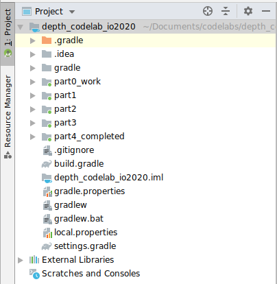
您將在 part0_work 模組中工作。此外,本程式碼研究室的每個部分都有完整解決方案。每個模組都是可建構的應用程式。
4. 執行範例應用程式
- 依序按一下「Run」(執行) >「Run...」(執行...) > ‘part0_work'。在顯示的「Select Deployment Target」對話方塊中,裝置應會列在「Connected Devices」下方。
- 選取裝置,然後按一下「OK」。Android Studio 會建構初始應用程式,並在裝置上執行。
- 應用程式會要求相機權限。輕觸「允許」即可繼續。

| 如何使用應用程式
|
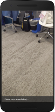
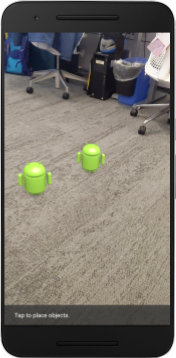
目前您的應用程式非常簡單,對現實世界場景幾何結構的瞭解不多。
舉例來說,如果您將 Android 人偶放在椅子後面,由於應用程式不知道椅子在那裡,應該要遮住 Android,因此算繪結果會顯示在椅子前面。
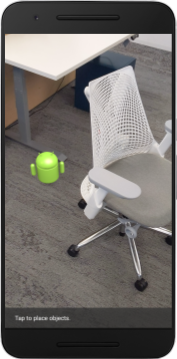
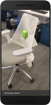
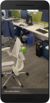
為修正這個問題,我們將使用 Depth API 提升這個應用程式的沉浸感和真實感。
5. 檢查是否支援 Depth API (第 1 部分)
ARCore Depth API 僅適用於部分支援的裝置。使用這些深度影像將功能整合至應用程式前,請先確認應用程式是在支援的裝置上執行。
在 DepthCodelabActivity 中新增私有成員,做為儲存目前裝置是否支援深度的旗標:
private boolean isDepthSupported;
我們可以在 onResume() 函式中填入這個旗標,並建立新的工作階段。
找出現有程式碼:
// Creates the ARCore session.
session = new Session(/* context= */ this);
將程式碼更新為:
// Creates the ARCore session.
session = new Session(/* context= */ this);
Config config = session.getConfig();
isDepthSupported = session.isDepthModeSupported(Config.DepthMode.AUTOMATIC);
if (isDepthSupported) {
  config.setDepthMode(Config.DepthMode.AUTOMATIC);
} else {
  config.setDepthMode(Config.DepthMode.DISABLED);
}
session.configure(config);
現在 AR 專案已完成適當設定,應用程式也知道是否可以使用以深度為基礎的功能。
此外,您也應讓使用者知道這個工作階段是否使用深度資料。
在 Snackbar 中新增另一則訊息。畫面底部會顯示以下內容:
// Add this line at the top of the file, with the other messages.
private static final String DEPTH_NOT_AVAILABLE_MESSAGE = "[Depth not supported on this device]";
在 onDrawFrame() 中,您可以視需要顯示這則訊息:
// Add this if-statement above messageSnackbarHelper.showMessage(this, messageToShow).
if (!isDepthSupported) {
  messageToShow += "\n" + DEPTH_NOT_AVAILABLE_MESSAGE;
}
如果應用程式在不支援深度的裝置上執行,您剛才新增的訊息會顯示在底部:

接著,您將更新應用程式,呼叫 Depth API 並擷取每個影格的深度圖片。
6. 擷取深度影像 (第 2 部分)
Depth API 會擷取裝置環境的 3D 觀測結果,並將含有該資料的深度圖片傳回應用程式。深度圖片中的每個像素都代表裝置相機與現實環境之間的距離測量結果。
現在您要使用這些深度圖片,改善應用程式中的算繪和視覺化效果。第一步是擷取每個影格的深度圖片,並繫結該紋理,供 GPU 使用。
首先,在專案中新增類別。DepthTextureHandler 負責擷取指定 ARCore 影格的深度圖片。
新增這個檔案:

src/main/java/com/google/ar/core/codelab/depth/DepthTextureHandler.java
package com.google.ar.core.codelab.depth;

import static android.opengl.GLES20.GL_CLAMP_TO_EDGE;
import static android.opengl.GLES20.GL_TEXTURE_2D;
import static android.opengl.GLES20.GL_TEXTURE_MAG_FILTER;
import static android.opengl.GLES20.GL_TEXTURE_MIN_FILTER;
import static android.opengl.GLES20.GL_TEXTURE_WRAP_S;
import static android.opengl.GLES20.GL_TEXTURE_WRAP_T;
import static android.opengl.GLES20.GL_UNSIGNED_BYTE;
import static android.opengl.GLES20.glBindTexture;
import static android.opengl.GLES20.glGenTextures;
import static android.opengl.GLES20.glTexImage2D;
import static android.opengl.GLES20.glTexParameteri;
import static android.opengl.GLES30.GL_LINEAR;
import static android.opengl.GLES30.GL_RG;
import static android.opengl.GLES30.GL_RG8;

import android.media.Image;
import com.google.ar.core.Frame;
import com.google.ar.core.exceptions.NotYetAvailableException;

/** Handle RG8 GPU texture containing a DEPTH16 depth image. */
public final class DepthTextureHandler {

  private int depthTextureId = -1;
  private int depthTextureWidth = -1;
  private int depthTextureHeight = -1;

  /**
   * Creates and initializes the depth texture. This method needs to be called on a
   * thread with a EGL context attached.
   */
  public void createOnGlThread() {
    int[] textureId = new int[1];
    glGenTextures(1, textureId, 0);
    depthTextureId = textureId[0];
    glBindTexture(GL_TEXTURE_2D, depthTextureId);
    glTexParameteri(GL_TEXTURE_2D, GL_TEXTURE_WRAP_S, GL_CLAMP_TO_EDGE);
    glTexParameteri(GL_TEXTURE_2D, GL_TEXTURE_WRAP_T, GL_CLAMP_TO_EDGE);
    glTexParameteri(GL_TEXTURE_2D, GL_TEXTURE_MIN_FILTER, GL_LINEAR);
    glTexParameteri(GL_TEXTURE_2D, GL_TEXTURE_MAG_FILTER, GL_LINEAR);
  }

  /**
   * Updates the depth texture with the content from acquireDepthImage16Bits().
   * This method needs to be called on a thread with an EGL context attached.
   */
  public void update(final Frame frame) {
    try {
      Image depthImage = frame.acquireDepthImage16Bits();
      depthTextureWidth = depthImage.getWidth();
      depthTextureHeight = depthImage.getHeight();
      glBindTexture(GL_TEXTURE_2D, depthTextureId);
      glTexImage2D(
          GL_TEXTURE_2D,
          0,
          GL_RG8,
          depthTextureWidth,
          depthTextureHeight,
          0,
          GL_RG,
          GL_UNSIGNED_BYTE,
          depthImage.getPlanes()[0].getBuffer());
      depthImage.close();
    } catch (NotYetAvailableException e) {
      // This normally means that depth data is not available yet.
    }
  }

  public int getDepthTexture() {
    return depthTextureId;
  }

  public int getDepthWidth() {
    return depthTextureWidth;
  }

  public int getDepthHeight() {
    return depthTextureHeight;
  }
}
現在,您要將這個類別的例項新增至 DepthCodelabActivity,確保每個影格都有深度圖像的副本,方便存取。
在 DepthCodelabActivity.java 中,將新類別的例項新增為私有成員變數:
private final DepthTextureHandler depthTexture = new DepthTextureHandler();
接著,更新 onSurfaceCreated() 方法來初始化這個紋理,以便 GPU 著色器使用:
// Put this at the top of the "try" block in onSurfaceCreated().
depthTexture.createOnGlThread();
最後,您要在每個影格中填入這個紋理,並使用最新的深度圖像,方法是在從 session 擷取的最新影格上呼叫您在上方建立的 update() 方法。
由於這個應用程式可選擇是否支援深度,因此只有在使用深度時,才需要使用這個呼叫。
// Add this just after "frame" is created inside onDrawFrame().
if (isDepthSupported) {
  depthTexture.update(frame);
}
現在您有深度圖像,且會隨著每個影格更新。著色器即可使用。
不過,應用程式的行為尚未改變。現在您將使用深度圖片來改善應用程式。
7. 算繪深度影像 (第 3 部分)
現在您有了深度圖像,接下來要看看圖像的樣子。在本節中,您將在應用程式中新增按鈕,以便為每個影格算繪深度。
新增著色器
查看深度影像的方式有很多種,下列著色器提供簡單的色彩對應視覺化效果。
| 新增 .vert 著色器在 Android Studio 中:
|


在新檔案中新增下列程式碼:
src/main/assets/shaders/background_show_depth_map.vert
attribute vec4 a_Position;
attribute vec2 a_TexCoord;

varying vec2 v_TexCoord;

void main() {
   v_TexCoord = a_TexCoord;
   gl_Position = a_Position;
}
在相同目錄中重複上述步驟,建立片段著色器並命名為 background_show_depth_map.frag。
將下列程式碼新增至這個新檔案:
src/main/assets/shaders/background_show_depth_map.frag
precision mediump float;
uniform sampler2D u_Depth;
varying vec2 v_TexCoord;
const highp float kMaxDepth = 20000.0; // In millimeters.

float GetDepthMillimeters(vec4 depth_pixel_value) {
  return 255.0 * (depth_pixel_value.r + depth_pixel_value.g * 256.0);
}

// Returns an interpolated color in a 6 degree polynomial interpolation.
vec3 GetPolynomialColor(in float x,
  in vec4 kRedVec4, in vec4 kGreenVec4, in vec4 kBlueVec4,
  in vec2 kRedVec2, in vec2 kGreenVec2, in vec2 kBlueVec2) {
  // Moves the color space a little bit to avoid pure red.
  // Removes this line for more contrast.
  x = clamp(x * 0.9 + 0.03, 0.0, 1.0);
  vec4 v4 = vec4(1.0, x, x * x, x * x * x);
  vec2 v2 = v4.zw * v4.z;
  return vec3(
    dot(v4, kRedVec4) + dot(v2, kRedVec2),
    dot(v4, kGreenVec4) + dot(v2, kGreenVec2),
    dot(v4, kBlueVec4) + dot(v2, kBlueVec2)
  );
}

// Returns a smooth Percept colormap based upon the Turbo colormap.
vec3 PerceptColormap(in float x) {
  const vec4 kRedVec4 = vec4(0.55305649, 3.00913185, -5.46192616, -11.11819092);
  const vec4 kGreenVec4 = vec4(0.16207513, 0.17712472, 15.24091500, -36.50657960);
  const vec4 kBlueVec4 = vec4(-0.05195877, 5.18000081, -30.94853351, 81.96403246);
  const vec2 kRedVec2 = vec2(27.81927491, -14.87899417);
  const vec2 kGreenVec2 = vec2(25.95549545, -5.02738237);
  const vec2 kBlueVec2 = vec2(-86.53476570, 30.23299484);
  const float kInvalidDepthThreshold = 0.01;
  return step(kInvalidDepthThreshold, x) *
         GetPolynomialColor(x, kRedVec4, kGreenVec4, kBlueVec4,
                            kRedVec2, kGreenVec2, kBlueVec2);
}

void main() {
  vec4 packed_depth = texture2D(u_Depth, v_TexCoord.xy);
  highp float depth_mm = GetDepthMillimeters(packed_depth);
  highp float normalized_depth = depth_mm / kMaxDepth;
  vec4 depth_color = vec4(PerceptColormap(normalized_depth), 1.0);
  gl_FragColor = depth_color;
}
接著,請更新 BackgroundRenderer 類別,以便使用 src/main/java/com/google/ar/core/codelab/common/rendering/BackgroundRenderer.java 中的這些新著色器。
在類別頂端新增著色器檔案路徑:
// Add these under the other shader names at the top of the class.
private static final String DEPTH_VERTEX_SHADER_NAME = "shaders/background_show_depth_map.vert";
private static final String DEPTH_FRAGMENT_SHADER_NAME = "shaders/background_show_depth_map.frag";
在 BackgroundRenderer 類別中新增更多成員變數,因為這會執行兩個著色器:
// Add to the top of file with the rest of the member variables.
private int depthProgram;
private int depthTextureParam;
private int depthTextureId = -1;
private int depthQuadPositionParam;
private int depthQuadTexCoordParam;
新增方法來填入這些欄位:
// Add this method below createOnGlThread().
public void createDepthShaders(Context context, int depthTextureId) throws IOException {
  int vertexShader =
      ShaderUtil.loadGLShader(
          TAG, context, GLES20.GL_VERTEX_SHADER, DEPTH_VERTEX_SHADER_NAME);
  int fragmentShader =
      ShaderUtil.loadGLShader(
          TAG, context, GLES20.GL_FRAGMENT_SHADER, DEPTH_FRAGMENT_SHADER_NAME);

  depthProgram = GLES20.glCreateProgram();
  GLES20.glAttachShader(depthProgram, vertexShader);
  GLES20.glAttachShader(depthProgram, fragmentShader);
  GLES20.glLinkProgram(depthProgram);
  GLES20.glUseProgram(depthProgram);
  ShaderUtil.checkGLError(TAG, "Program creation");

  depthTextureParam = GLES20.glGetUniformLocation(depthProgram, "u_Depth");
  ShaderUtil.checkGLError(TAG, "Program parameters");

  depthQuadPositionParam = GLES20.glGetAttribLocation(depthProgram, "a_Position");
  depthQuadTexCoordParam = GLES20.glGetAttribLocation(depthProgram, "a_TexCoord");

  this.depthTextureId = depthTextureId;
}
新增這個方法,用於在每個影格上使用這些著色器繪製內容:
// Put this at the bottom of the file.
public void drawDepth(@NonNull Frame frame) {
  if (frame.hasDisplayGeometryChanged()) {
    frame.transformCoordinates2d(
        Coordinates2d.OPENGL_NORMALIZED_DEVICE_COORDINATES,
        quadCoords,
        Coordinates2d.TEXTURE_NORMALIZED,
        quadTexCoords);
  }

  if (frame.getTimestamp() == 0 || depthTextureId == -1) {
    return;
  }

  // Ensure position is rewound before use.
  quadTexCoords.position(0);

  // No need to test or write depth, the screen quad has arbitrary depth, and is expected
  // to be drawn first.
  GLES20.glDisable(GLES20.GL_DEPTH_TEST);
  GLES20.glDepthMask(false);

  GLES20.glActiveTexture(GLES20.GL_TEXTURE0);
  GLES20.glBindTexture(GLES20.GL_TEXTURE_2D, depthTextureId);
  GLES20.glUseProgram(depthProgram);
  GLES20.glUniform1i(depthTextureParam, 0);

  // Set the vertex positions and texture coordinates.
  GLES20.glVertexAttribPointer(
        depthQuadPositionParam, COORDS_PER_VERTEX, GLES20.GL_FLOAT, false, 0, quadCoords);
  GLES20.glVertexAttribPointer(
        depthQuadTexCoordParam, TEXCOORDS_PER_VERTEX, GLES20.GL_FLOAT, false, 0, quadTexCoords);

  // Draws the quad.
  GLES20.glEnableVertexAttribArray(depthQuadPositionParam);
  GLES20.glEnableVertexAttribArray(depthQuadTexCoordParam);
  GLES20.glDrawArrays(GLES20.GL_TRIANGLE_STRIP, 0, 4);
  GLES20.glDisableVertexAttribArray(depthQuadPositionParam);
  GLES20.glDisableVertexAttribArray(depthQuadTexCoordParam);

  // Restore the depth state for further drawing.
  GLES20.glDepthMask(true);
  GLES20.glEnable(GLES20.GL_DEPTH_TEST);

  ShaderUtil.checkGLError(TAG, "BackgroundRendererDraw");
}
新增切換按鈕
現在您已具備算繪深度地圖的能力,請善加利用!新增可切換這個算繪功能的按鈕。
在 DepthCodelabActivity 檔案頂端,新增要使用的按鈕匯入項目:
import android.widget.Button;
更新類別,新增布林值成員,指出是否已切換深度算繪 (預設為關閉):
private boolean showDepthMap = false;
接著,在 onCreate() 方法結尾新增按鈕,控制 showDepthMap 布林值:
final Button toggleDepthButton = (Button) findViewById(R.id.toggle_depth_button);
    toggleDepthButton.setOnClickListener(
        view -> {
          if (isDepthSupported) {
            showDepthMap = !showDepthMap;
            toggleDepthButton.setText(showDepthMap ? R.string.hide_depth : R.string.show_depth);
          } else {
            showDepthMap = false;
            toggleDepthButton.setText(R.string.depth_not_available);
          }
        });
在 res/values/strings.xml 中新增下列字串:
<string translatable="false" name="show_depth">Show Depth</string>
<string translatable="false" name="hide_depth">Hide Depth</string>
<string translatable="false" name="depth_not_available">Depth Not Available</string>
在 res/layout/activity_main.xml 中,將這個按鈕新增至應用程式版面配置底部:
<Button
    android:id="@+id/toggle_depth_button"
    android:layout_width="wrap_content"
    android:layout_height="wrap_content"
    android:layout_margin="20dp"
    android:gravity="center"
    android:text="@string/show_depth"
    android:layout_alignParentRight="true"
    android:layout_alignParentTop="true"/>
按鈕現在會控制布林值 showDepthMap 的值。使用這個旗標控制是否要算繪深度地圖。
返回 DepthCodelabActivity 中的 onDrawFrame() 方法,並新增:
// Add this snippet just under backgroundRenderer.draw(frame);
if (showDepthMap) {
  backgroundRenderer.drawDepth(frame);
}
在 onSurfaceCreated() 中加入下列程式碼,將深度紋理傳遞至 backgroundRenderer:
// Add to onSurfaceCreated() after backgroundRenderer.createonGlThread(/*context=*/ this);
backgroundRenderer.createDepthShaders(/*context=*/ this, depthTexture.getDepthTexture());
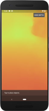
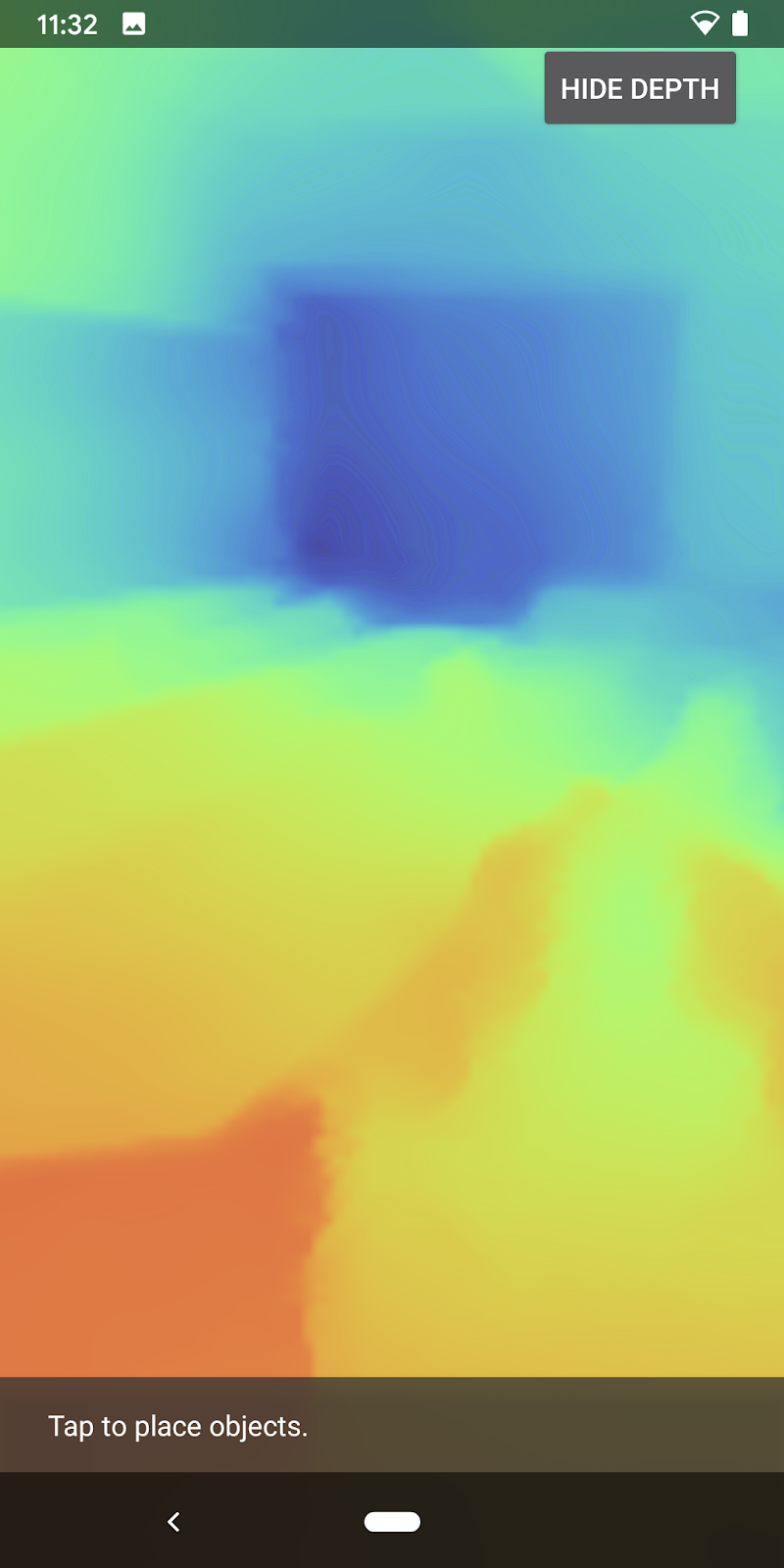
現在只要按下畫面右上角的按鈕,即可查看每個影格的深度影像。
|
| ||
在沒有 Depth API 支援的情況下執行 | 支援 Depth API 的執行方式 | ||

[選用] 華麗的景深動畫
應用程式目前會直接顯示深度圖。紅色像素代表鄰近區域。藍色像素代表遠處區域。
|
|

傳達深度資訊的方法有很多種,在本節中,您將修改著色器,只顯示不斷遠離攝影機的頻帶內的深度,藉此定期脈衝深度。
首先,在 background_show_depth_map.frag 的頂端新增下列變數:
uniform float u_DepthRangeToRenderMm;
const float kDepthWidthToRenderMm = 350.0;
- 然後使用這些值,在著色器的
main()函式中,篩選要以深度值涵蓋的像素:
// Add this line at the end of main().
gl_FragColor.a = clamp(1.0 - abs((depth_mm - u_DepthRangeToRenderMm) / kDepthWidthToRenderMm), 0.0, 1.0);
接著,更新 BackgroundRenderer.java 以保留這些著色器參數。在類別頂端新增下列欄位:
private static final float MAX_DEPTH_RANGE_TO_RENDER_MM = 20000.0f;
private float depthRangeToRenderMm = 0.0f;
private int depthRangeToRenderMmParam;
在 createDepthShaders() 方法中,新增下列內容,將這些參數與著色器程式相符:
depthRangeToRenderMmParam = GLES20.glGetUniformLocation(depthProgram, "u_DepthRangeToRenderMm");
- 最後,您可以在
drawDepth()方法中控制這段時間範圍。新增下列程式碼,每次繪製影格時,這個範圍就會遞增:
// Enables alpha blending.
GLES20.glEnable(GLES20.GL_BLEND);
GLES20.glBlendFunc(GLES20.GL_SRC_ALPHA, GLES20.GL_ONE_MINUS_SRC_ALPHA);

// Updates range each time draw() is called.
depthRangeToRenderMm += 50.0f;
if (depthRangeToRenderMm > MAX_DEPTH_RANGE_TO_RENDER_MM) {
  depthRangeToRenderMm = 0.0f;
}

// Passes latest value to the shader.
GLES20.glUniform1f(depthRangeToRenderMmParam, depthRangeToRenderMm);
現在,深度會以動畫脈衝的形式呈現,流經整個場景。
您可以隨意變更這裡提供的值,讓脈衝變慢、變快、變寬、變窄等。您也可以嘗試探索全新的方法來變更著色器,以顯示深度資訊!
8. 使用 Depth API 進行遮蔽 (第 4 部分)
現在,您要在應用程式中處理物件遮蔽情形。
遮蔽是指虛擬物體無法完整算繪,因為虛擬物體和攝影機之間有實體物體。管理遮蔽是打造沉浸式 AR 體驗的必要條件。
即時正確地算繪虛擬物件,可提升擴增實境場景的真實感和可信度。如需更多範例,請參閱這部影片,瞭解如何使用 Depth API 混合現實。
在本節中,您將更新應用程式,只在深度資訊可用時加入虛擬物件。
新增物件著色器
與前幾個部分一樣,您將新增支援深度資訊的著色器。這次您可以複製現有的物件著色器,並新增遮蔽功能。
請務必保留這兩個版本的物件著色器,這樣應用程式才能在執行階段決定是否支援深度。
在 src/main/assets/shaders 目錄中複製 object.vert 和 object.frag 著色器檔案。
|
|
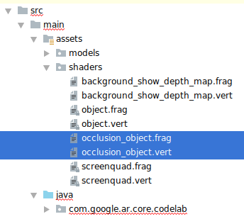
在 occlusion_object.vert 中,於 main() 上方新增下列變數:
varying vec3 v_ScreenSpacePosition;
在 main() 底部設定這個變數:
v_ScreenSpacePosition = gl_Position.xyz / gl_Position.w;
在檔案頂端,於 main() 上方新增下列變數,即可更新 occlusion_object.frag:
varying vec3 v_ScreenSpacePosition;

uniform sampler2D u_Depth;
uniform mat3 u_UvTransform;
uniform float u_DepthTolerancePerMm;
uniform float u_OcclusionAlpha;
uniform float u_DepthAspectRatio;
- 在著色器中的
main()上方新增這些輔助函式,方便處理深度資訊:
float GetDepthMillimeters(in vec2 depth_uv) {
  // Depth is packed into the red and green components of its texture.
  // The texture is a normalized format, storing millimeters.
  vec3 packedDepthAndVisibility = texture2D(u_Depth, depth_uv).xyz;
  return dot(packedDepthAndVisibility.xy, vec2(255.0, 256.0 * 255.0));
}

// Returns linear interpolation position of value between min and max bounds.
// E.g., InverseLerp(1100, 1000, 2000) returns 0.1.
float InverseLerp(in float value, in float min_bound, in float max_bound) {
  return clamp((value - min_bound) / (max_bound - min_bound), 0.0, 1.0);
}

// Returns a value between 0.0 (not visible) and 1.0 (completely visible)
// Which represents how visible or occluded is the pixel in relation to the
// depth map.
float GetVisibility(in vec2 depth_uv, in float asset_depth_mm) {
  float depth_mm = GetDepthMillimeters(depth_uv);

  // Instead of a hard z-buffer test, allow the asset to fade into the
  // background along a 2 * u_DepthTolerancePerMm * asset_depth_mm
  // range centered on the background depth.
  float visibility_occlusion = clamp(0.5 * (depth_mm - asset_depth_mm) /
    (u_DepthTolerancePerMm * asset_depth_mm) + 0.5, 0.0, 1.0);

  // Depth close to zero is most likely invalid, do not use it for occlusions.
  float visibility_depth_near = 1.0 - InverseLerp(
      depth_mm, /*min_depth_mm=*/150.0, /*max_depth_mm=*/200.0);

  // Same for very high depth values.
  float visibility_depth_far = InverseLerp(
      depth_mm, /*min_depth_mm=*/17500.0, /*max_depth_mm=*/20000.0);

  float visibility =
    max(max(visibility_occlusion, u_OcclusionAlpha),
      max(visibility_depth_near, visibility_depth_far));

  return visibility;
}
現在,請將 occlusion_object.frag 中的 main() 更新為可感知深度並套用遮蔽效果。在檔案底部新增下列幾行:
const float kMToMm = 1000.0;
float asset_depth_mm = v_ViewPosition.z * kMToMm * -1.;
vec2 depth_uvs = (u_UvTransform * vec3(v_ScreenSpacePosition.xy, 1)).xy;
gl_FragColor.a *= GetVisibility(depth_uvs, asset_depth_mm);
現在您已取得新版物件著色器,可以修改算繪器程式碼。
算繪物件遮蔽
接著複製 ObjectRenderer 中的 src/main/java/com/google/ar/core/codelab/common/rendering/ObjectRenderer.java 類別。
- 選取
ObjectRenderer類別 - 按一下滑鼠右鍵 >「複製」
- 選取「rendering」資料夾
- 按一下滑鼠右鍵 >「貼上」

- 將類別重新命名為
OcclusionObjectRenderer

重新命名的新類別現在應該會顯示在同一個資料夾中:

開啟新建立的 OcclusionObjectRenderer.java,然後變更檔案頂端的著色器路徑:
private static final String VERTEX_SHADER_NAME = "shaders/occlusion_object.vert";
private static final String FRAGMENT_SHADER_NAME = "shaders/occlusion_object.frag";
- 在類別頂端新增這些與深度相關的成員變數。變數會調整遮蔽邊界的銳利度。
// Shader location: depth texture
private int depthTextureUniform;

// Shader location: transform to depth uvs
private int depthUvTransformUniform;

// Shader location: depth tolerance property
private int depthToleranceUniform;

// Shader location: maximum transparency for the occluded part.
private int occlusionAlphaUniform;

private int depthAspectRatioUniform;

private float[] uvTransform = null;
private int depthTextureId;
在類別頂端建立這些成員變數,並設定預設值:
// These values will be changed each frame based on the distance to the object.
private float depthAspectRatio = 0.0f;
private final float depthTolerancePerMm = 0.015f;
private final float occlusionsAlpha = 0.0f;
在 createOnGlThread() 方法中,初始化著色器的統一參數:
// Occlusions Uniforms.  Add these lines before the first call to ShaderUtil.checkGLError
// inside the createOnGlThread() method.
depthTextureUniform = GLES20.glGetUniformLocation(program, "u_Depth");
depthUvTransformUniform = GLES20.glGetUniformLocation(program, "u_UvTransform");
depthToleranceUniform = GLES20.glGetUniformLocation(program, "u_DepthTolerancePerMm");
occlusionAlphaUniform = GLES20.glGetUniformLocation(program, "u_OcclusionAlpha");
depthAspectRatioUniform = GLES20.glGetUniformLocation(program, "u_DepthAspectRatio");
- 請更新
draw()方法,確保每次繪製這些值時都會更新:
// Add after other GLES20.glUniform calls inside draw().
GLES20.glActiveTexture(GLES20.GL_TEXTURE1);
GLES20.glBindTexture(GLES20.GL_TEXTURE_2D, depthTextureId);
GLES20.glUniform1i(depthTextureUniform, 1);
GLES20.glUniformMatrix3fv(depthUvTransformUniform, 1, false, uvTransform, 0);
GLES20.glUniform1f(depthToleranceUniform, depthTolerancePerMm);
GLES20.glUniform1f(occlusionAlphaUniform, occlusionsAlpha);
GLES20.glUniform1f(depthAspectRatioUniform, depthAspectRatio);
在 draw() 中新增下列幾行,即可在算繪時啟用混合模式,以便在虛擬物件遭到遮蔽時套用透明度:
// Add these lines just below the code-block labeled "Enable vertex arrays"
GLES20.glEnable(GLES20.GL_BLEND);
GLES20.glBlendFunc(GLES20.GL_SRC_ALPHA, GLES20.GL_ONE_MINUS_SRC_ALPHA);
// Add these lines just above the code-block labeled "Disable vertex arrays"
GLES20.glDisable(GLES20.GL_BLEND);
GLES20.glDepthMask(true);
- 新增下列方法,讓
OcclusionObjectRenderer的呼叫端提供深度資訊:
// Add these methods at the bottom of the OcclusionObjectRenderer class.
public void setUvTransformMatrix(float[] transform) {
  uvTransform = transform;
}

public void setDepthTexture(int textureId, int width, int height) {
  depthTextureId = textureId;
  depthAspectRatio = (float) width / (float) height;
}
控制物件遮蔽
現在您有了新的 OcclusionObjectRenderer,可以將其新增至 DepthCodelabActivity,並選擇何時及如何採用遮蔽算繪。
在活動中新增 OcclusionObjectRenderer 的執行個體,即可啟用這項邏輯,讓 ObjectRenderer 和 OcclusionObjectRenderer 成為 DepthCodelabActivity 的成員:
// Add this include at the top of the file.
import com.google.ar.core.codelab.common.rendering.OcclusionObjectRenderer;
// Add this member just below the existing "virtualObject", so both are present.
private final OcclusionObjectRenderer occludedVirtualObject = new OcclusionObjectRenderer();
- 接下來,您可以根據目前的裝置是否支援 Depth API,控制何時使用這個
occludedVirtualObject。在onSurfaceCreated方法中,於設定virtualObject的下方新增下列程式碼:
if (isDepthSupported) {
  occludedVirtualObject.createOnGlThread(/*context=*/ this, "models/andy.obj", "models/andy.png");
  occludedVirtualObject.setDepthTexture(
     depthTexture.getDepthTexture(),
     depthTexture.getDepthWidth(),
     depthTexture.getDepthHeight());
  occludedVirtualObject.setMaterialProperties(0.0f, 2.0f, 0.5f, 6.0f);
}
如果裝置不支援深度,系統會建立 occludedVirtualObject 例項,但不會使用。在具備深度的手機上,這兩個版本都會初始化,並在繪製時決定要使用哪個版本的轉譯器。
在 onDrawFrame() 方法中,找出下列現有程式碼:
virtualObject.updateModelMatrix(anchorMatrix, scaleFactor);
virtualObject.draw(viewmtx, projmtx, colorCorrectionRgba, OBJECT_COLOR);
將這段程式碼替換為下列程式碼:
if (isDepthSupported) {
  occludedVirtualObject.updateModelMatrix(anchorMatrix, scaleFactor);
  occludedVirtualObject.draw(viewmtx, projmtx, colorCorrectionRgba, OBJECT_COLOR);
} else {
  virtualObject.updateModelMatrix(anchorMatrix, scaleFactor);
  virtualObject.draw(viewmtx, projmtx, colorCorrectionRgba, OBJECT_COLOR);
}
最後,請確認深度影像已正確對應至輸出算繪。由於深度影像的解析度可能與螢幕不同,長寬比也可能不同,因此深度影像和相機影像的紋理座標可能不同。
- 在檔案底部新增 Helper 方法
getTextureTransformMatrix()。這個方法會傳回轉換矩陣,套用後,螢幕空間 UV 會與用於算繪攝影機動態饋給的四邊形紋理座標正確相符。也會將裝置螢幕方向納入考量。
private static float[] getTextureTransformMatrix(Frame frame) {
  float[] frameTransform = new float[6];
  float[] uvTransform = new float[9];
  // XY pairs of coordinates in NDC space that constitute the origin and points along the two
  // principal axes.
  float[] ndcBasis = {0, 0, 1, 0, 0, 1};

  // Temporarily store the transformed points into outputTransform.
  frame.transformCoordinates2d(
      Coordinates2d.OPENGL_NORMALIZED_DEVICE_COORDINATES,
      ndcBasis,
      Coordinates2d.TEXTURE_NORMALIZED,
      frameTransform);

  // Convert the transformed points into an affine transform and transpose it.
  float ndcOriginX = frameTransform[0];
  float ndcOriginY = frameTransform[1];
  uvTransform[0] = frameTransform[2] - ndcOriginX;
  uvTransform[1] = frameTransform[3] - ndcOriginY;
  uvTransform[2] = 0;
  uvTransform[3] = frameTransform[4] - ndcOriginX;
  uvTransform[4] = frameTransform[5] - ndcOriginY;
  uvTransform[5] = 0;
  uvTransform[6] = ndcOriginX;
  uvTransform[7] = ndcOriginY;
  uvTransform[8] = 1;

  return uvTransform;
}
getTextureTransformMatrix() 需要在檔案頂端匯入下列項目:
import com.google.ar.core.Coordinates2d;
每當螢幕紋理變更 (例如螢幕旋轉時),您都想計算這些紋理座標之間的轉換。這項功能設有使用限制。
在檔案頂端新增下列標記:
// Add this member at the top of the file.
private boolean calculateUVTransform = true;
- 在
onDrawFrame()內,檢查是否需要在建立影格和攝影機後重新計算儲存的轉換:
// Add these lines inside onDrawFrame() after frame.getCamera().
if (frame.hasDisplayGeometryChanged() || calculateUVTransform) {
  calculateUVTransform = false;
  float[] transform = getTextureTransformMatrix(frame);
  occludedVirtualObject.setUvTransformMatrix(transform);
}
完成這些變更後,您現在可以執行應用程式,並使用虛擬物件遮蔽功能!
現在,您的應用程式應該可以在所有手機上順利執行,並在支援時自動使用遮蔽深度。
|
| ||
執行支援 Depth API 的應用程式 | 在不支援 Depth API 的裝置上執行應用程式 | ||


9. [選用] 提升遮蔽品質
上述實作的深度遮蔽方法會提供邊界銳利的遮蔽效果。相機距離物體越遠,深度測量結果就越不準確,可能會導致視覺效果失真。
我們可以在遮蔽測試中加入額外的模糊效果,讓隱藏的虛擬物體邊緣更平滑,藉此減輕這個問題。
occlusion_object.frag
在 occlusion_object.frag 頂端新增下列統一變數:
uniform float u_OcclusionBlurAmount;
在著色器中的 main() 正上方新增這個輔助函式,將核心模糊套用至遮蔽取樣:
float GetBlurredVisibilityAroundUV(in vec2 uv, in float asset_depth_mm) {
  // Kernel used:
  // 0   4   7   4   0
  // 4   16  26  16  4
  // 7   26  41  26  7
  // 4   16  26  16  4
  // 0   4   7   4   0
  const float kKernelTotalWeights = 269.0;
  float sum = 0.0;

  vec2 blurriness = vec2(u_OcclusionBlurAmount,
                         u_OcclusionBlurAmount * u_DepthAspectRatio);

  float current = 0.0;

  current += GetVisibility(uv + vec2(-1.0, -2.0) * blurriness, asset_depth_mm);
  current += GetVisibility(uv + vec2(+1.0, -2.0) * blurriness, asset_depth_mm);
  current += GetVisibility(uv + vec2(-1.0, +2.0) * blurriness, asset_depth_mm);
  current += GetVisibility(uv + vec2(+1.0, +2.0) * blurriness, asset_depth_mm);
  current += GetVisibility(uv + vec2(-2.0, +1.0) * blurriness, asset_depth_mm);
  current += GetVisibility(uv + vec2(+2.0, +1.0) * blurriness, asset_depth_mm);
  current += GetVisibility(uv + vec2(-2.0, -1.0) * blurriness, asset_depth_mm);
  current += GetVisibility(uv + vec2(+2.0, -1.0) * blurriness, asset_depth_mm);
  sum += current * 4.0;

  current = 0.0;
  current += GetVisibility(uv + vec2(-2.0, -0.0) * blurriness, asset_depth_mm);
  current += GetVisibility(uv + vec2(+2.0, +0.0) * blurriness, asset_depth_mm);
  current += GetVisibility(uv + vec2(+0.0, +2.0) * blurriness, asset_depth_mm);
  current += GetVisibility(uv + vec2(-0.0, -2.0) * blurriness, asset_depth_mm);
  sum += current * 7.0;

  current = 0.0;
  current += GetVisibility(uv + vec2(-1.0, -1.0) * blurriness, asset_depth_mm);
  current += GetVisibility(uv + vec2(+1.0, -1.0) * blurriness, asset_depth_mm);
  current += GetVisibility(uv + vec2(-1.0, +1.0) * blurriness, asset_depth_mm);
  current += GetVisibility(uv + vec2(+1.0, +1.0) * blurriness, asset_depth_mm);
  sum += current * 16.0;

  current = 0.0;
  current += GetVisibility(uv + vec2(+0.0, +1.0) * blurriness, asset_depth_mm);
  current += GetVisibility(uv + vec2(-0.0, -1.0) * blurriness, asset_depth_mm);
  current += GetVisibility(uv + vec2(-1.0, -0.0) * blurriness, asset_depth_mm);
  current += GetVisibility(uv + vec2(+1.0, +0.0) * blurriness, asset_depth_mm);
  sum += current * 26.0;

  sum += GetVisibility(uv , asset_depth_mm) * 41.0;

  return sum / kKernelTotalWeights;
}
在 main() 中替換現有這一行:
gl_FragColor.a *= GetVisibility(depth_uvs, asset_depth_mm);
取代為:
gl_FragColor.a *= GetBlurredVisibilityAroundUV(depth_uvs, asset_depth_mm);
更新算繪器,即可使用這項新的著色器功能。
OcclusionObjectRenderer.java
在類別頂端新增下列成員變數:
private int occlusionBlurUniform;
private final float occlusionsBlur = 0.01f;
在 createOnGlThread 方法中加入以下內容:
// Add alongside the other calls to GLES20.glGetUniformLocation.
occlusionBlurUniform = GLES20.glGetUniformLocation(program, "u_OcclusionBlurAmount");
在 draw 方法中加入以下內容:
// Add alongside the other calls to GLES20.glUniform1f.
GLES20.glUniform1f(occlusionBlurUniform, occlusionsBlur);
| 視覺比較進行這些變更後,遮蔽邊界應該會更加平滑。 |
10. 建構、執行、測試
建構並執行應用程式
- 透過 USB 連接 Android 裝置。
- 依序選擇「File」>「Build and Run」。
- 另存新檔:ARCodeLab.apk。
- 等待應用程式建構完成並部署到裝置。
首次嘗試將應用程式部署至裝置時:
- 你必須在裝置上「允許 USB 偵錯」。選取「確定」即可繼續。
- 系統會詢問您是否要授予應用程式裝置攝影機的使用權限。授予存取權,即可繼續使用 AR 功能。
測試應用程式
執行應用程式時,您可以握住裝置、在空間中移動,並緩慢掃描某個區域,測試應用程式的基本行為。請嘗試收集至少 10 秒的資料,並從多個方向掃描該區域,再進行下一個步驟。
疑難排解
設定 Android 裝置以進行開發
- 使用 USB 傳輸線將裝置連接至開發機器。如果您使用 Windows 進行開發,可能需要為裝置安裝適當的 USB 驅動程式。
- 在「開發人員選項」視窗中執行下列步驟,啟用「USB 偵錯」:
- 開啟「設定」應用程式。
- 如果裝置使用 Android 8.0 以上版本,請選取「系統」。否則,請繼續下一步。
- 捲動至底部,然後選取「關於手機」。
- 捲動至底部,然後輕觸「版本號碼」 7 次。
- 返回上一個畫面並捲動至底部,然後輕觸「開發人員選項」。
- 在「開發人員選項」視窗中,向下捲動並啟用「USB 偵錯」。
如要進一步瞭解這個程序,請前往 Google 的 Android 開發人員網站。
與授權相關的建構失敗

如果遇到與授權相關的建構失敗問題 (Failed to install the following Android SDK packages as some licences have not been accepted),可以使用下列指令查看並接受這些授權:
cd <path to Android SDK>
tools/bin/sdkmanager --licenses
11. 恭喜
恭喜,您已成功使用 Google 的 ARCore Depth API,建構及執行第一個以深度為基礎的擴增實境應用程式!